OBJECTIVE: To verify theoretical analysis of a 3 pinned
portal frame by experimental evaluation.
1.
Portal frame apparatus.
2.
Weight of 5N load.
Portal
frame apparatus to verify theoretical analysis of a 3 pinned portal frame by
experimental evaluation.

Source:
https://www.scribd.com/document/256542933/Lab-Report-Portal-Frame
the
digital indicator is connected to load cell. The indicator must be switched on
for 10 minutes before taking readings. Load is applied to the load hanger, and
then indicator reading represents the horizontal reaction of the pinned
support. There is tare button when there is not a zero error then it should be
pressed. B y increasing Load on hanger then change in the horizontal reaction
is recorded.
1. Weight to verify theoretical analysis
of a 3 pinned portal frame by experimental evaluation.

Source:
https://www.scribd.com/document/256542933/Lab-Report-Portal-Frame
Weight should be free
from any dust or any scratch because it effect on the readings.
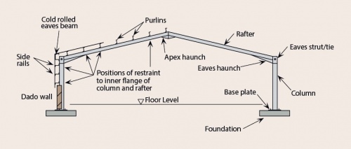
Portable frame method:
It
is used for the analysis of approximate lateral load. Several engineering
structures like factories, building and bridges used this method for the
testing of horizontal and vertical loads. This method is dominant in low rise
structure. It makes simplifying assumptions in columns.

Source: https://www.steelconstruction.info/images/thumb/8/8e/Portal-2.jpg/500px-Portal-2.jpg
Shear force:
It
is the unaligned forces pushing one part of a body in one specific direction,
and other part of the body in the opposite direction. When the forces are
aligned into each other then this force is called compression force. Shear
force in the beam is the algebraic sum of all the forces including reactions
acting normal to the axis of the beam either on the left or right side of the
beam.
Bending moment diagram:
It
always use by the structural engineers. In steel beam design, bending moment
tells the structural engineer that which lightest shape of steel that can be
use. For simply supported beam, maximum bending moment is located at the point
where shear is zero because shear is the mathematical derivative of shear.

Source: https://i.pinimg.com/originals/e3/88/06/e38806523fa6ef891784c198d01e9bf4.jpg
Calculation
of shear force and bending moment diagram of assume portal frame:
The
portal frame has two pinned joints and one roller support at one end. When we
loaded the frame, the roller pins allow the frame to move sideways. A
horizontal force can be applied to restore the end of the frame to its original
position. So this action can be simulate by the action of a pinned support, now
frame has 3 pinned joints.
To
Find to
verify theoretical analysis of a 3 pinned portal frame by experimental
evaluation.
Horizontal
reaction =______
Vertical
reaction =______
Shear
Force and Bending Moment Diagram=______
ASSUME PORTAL FRAME:


Experimental procedure to
verify theoretical analysis of a 3 pinned portal frame by experimental
evaluation.
1. Load
should be applied in intervals.
2. The
indicator reading shows the horizontal reaction of the pinned support.
3. By
increasing the load on the load hanger the change in the horizontal reaction is
recorded.
4. Take
readings for four load increments.
5. Then
results of the experiment should be related with the theoretical readings to
find the error.
Calculations to verify theoretical analysis of a 3 pinned portal frame by experimental
evaluation.

Width, b = 25mm
Thickness, h = 9mm
Height
of portal frame, L1 = 600mm
Length
of portal frame, L3 = 600mm
Distance
of load from support A, a = 500mm

From
the graph, the slope of the experiment is 0.04
 Error = (theoretical –
experimental) / (theoretical) × 100
Error = (theoretical –
experimental) / (theoretical) × 100
Error
= (0.0417 – 0.04) / (0.0417)  100
100
Error
= 4.08
Theoretical
horizontal support reaction (N) is greater than experimental horizontal support
reaction (N) because it is free from any error.
Sources or errors to verify theoretical analysis of a 3 pinned portal frame by
experimental evaluation.
Normally
errors in the measurement are due to systematic error, random error, and
blunders (misreading a scale or forgetting a digit while reading a scale).
These errors can be eliminating by taking more readings or by taking more
observations. Use system which is up-to-date for eliminating system error. This
error can also be eliminating by taking observation from another instrument.
Conclusion to verify theoretical analysis of a 3 pinned portal frame by
experimental evaluation.
From
the result, we conclude that experiment contains small error. Few suggestions
should be applied for getting accurate results. Following are the suggestion:
1. Carefully
applied weights
2. Readings
should be observed accurately.
From
experiment we get that by increasing loads there will be increase in displacement
on the roller side and it will increase the bending moment on the roller side.


